If you are a regular blog follower then you will have probably been fascinated last week by my post on circuits and learning “What’s a watt?”
Well I hope you learned as much as I did. My mind was further expanded this week when we talked about wire sizing and fuses.
I guess I have managed to live all my 41 years on this earth and have never really considered why some things have smaller wires than others. Well now I know…
First of all, before we get to the size of wire thing, Chris (our tutor) from Tweeds Marine recommends that every boat should have an electrical diagram showing the location of all the electrical things on board and how they are hooked up. You might also want to add the location of the wires (and perhaps their colours). You should try and draw the plan to scale so that you can use your diagram for measuring distances (like how much wire you might need).
Here is a pic of what an electrical diagram might look like:
And here is a link to a blank boat outline that you might like to print out to make a start on your diagram.
If you google ‘Marine electrical diagram’ you will see that there are heaps of different ways of doing a plan. So just do one that makes sense to you (and any other people that might be working on your boat in the future).
So before you go adding any new things to your electrical systems, you need to figure a few things out. You simply can’t just go and choose some cool looking wire and stick it on to an electrical thing and expect it to work. (Good to know this…)
Thin wires provide more resistance, they are cheaper to buy, less bulky and good for non-critical things on board. They have a “high voltage drop”.
Thicker wires are heavier and more expensive. They allow more current to flow through and are good for critical items. They have a “low voltage drop”.
“So what on earth is voltage drop?” I hear you ask. Good question! I was wondering the same thing too. Well it means that some of the voltage that is coming out of the battery gets lost along the way around the circuit. Be it through the wire itself, or to other things that it is connected to.
Or in more technical language: Voltage drop describes how the supplied energy of a voltage source is reduced as electric current moves through the passive elements (elements that do not supply voltage) of an electrical circuit.
Blog follower Allan also has a good analogy:
“A load has a resistance to make it work. Consider resistance like friction is to a car. If we have no friction between the road and the tyres, the car would spin it’s wheels and go no where. So the friction is the resistance to the movement of the tyres and makes the car move forward. But at the same time, friction is the enemy, because opposing that movement is resistance to the movement. This is seen as heat. The tyres get hot while moving the car as the power the engine develops is being “pushed” into the road surface.
A wire is the same. So a load (lets say a winch motor) has a high amount of resistance. Simply because the power of something is a sum of it’s resistance and voltage, which equates to the current required to make it work. So you have to supply a large amount of power to make the motor work. That resistance to working is transposed over the length of the wire that feeds the power to the motor.
Lets say 1000 watts of power is required to work the motor. That 1000W @12V = a current required of 84Amps. That resistance of that motor would be just 0.144ohms. Now lets say the wire (or cable in this case) had a resistance of 1ohm over its length. That 0.144Ohms is transposed over the length of the cable. So now there is a total resistance of 1.144ohms over all. The current is now shared over the length of the wire and that 1ohm would equate to well over 50A of current being dissipated over that cable. That equates to 648W of power in that cable. Power results in heat energy, so we have 648W of heat being developed in the cable instead of getting to the motor.
The motor is only getting 352W of energy, which is likely to make it stall. All just because there is 1 tiny ohm of resistance in that cable. And by the way, when a motor stalls, the current required goes up and so the load becomes even greater and hence even more power is dissipated over the length of the cable and the heat becomes greater and it’s a never ending death spiral till something gives.
So all wire has a resistance per metre. Lets say for ease, it is 1 ohm per 1 metre. So it would be 2 ohms per 2m and 4 ohms per 4metres. So the energy would now be calculated over say 4ohms 4m. So you could imagine the Power loss, the motor would hardly do a thing. To reduce that resistance, you have to increase the wire diameter so more current can flow and get to the motor where the work needs to be done, not be seen as wasted heat in the cable.”
Great thanks Alan! I think I have got it now!
Check out this chart below.
You will see along the top it says circuit type – ‘non-critical – 10% voltage drop’, or ‘critical 3% voltage drop’.
I guess we could assume that our stereo is non-critical (unless you are well known as being the ‘party boat’ and then you might have different ideas.)
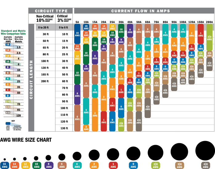
The line along the top it talks about current flow in amps. You need to figure out what power your stereo needs. A quick google search suggests a stereo might draw around 6amps.
Then you need to think about how far the wire has to travel – from the battery/fuse board, up to the stereo and then back to the fuse board again. In my boat I’d estimate it would be around five metres. (Not sure about the speakers and whether we have to factor them in to the equation as well – in which case there is going to be a LOT more wire) I will ask that question at our next class.
So we look along the top line to find 6 amps (somewhere between 5 & 10) and then down the non-critical line to how long our wire is going to be – in our case 5 metres (so somewhere between 0-20ft) and you can see we will need a size #16 AWG wire (AWG stands for American Wire Gauge) The little table on the far left hand size then translates the American size in to metric if needed.
So now you can go out and buy your wire – remember to get marine grade – tinned copper wire.
Apparently if you have something that draws a lot of power and needs to go a long way you might have to end up having multiple (bundle) wires. This is getting a bit complicated. Give Chris at Tweeds Marine a call to sort you out.
Ok test time! Using the table, what wire size would you need to use for a critical system that draws 50 amps and the wire is going to be about 15 metres (50′) long? (Answer below)
But we aren’t out of the woods yet… before we hit the shop we have to choose what kind of fuse we are going to have as well!
Why do we need fuses? Well a fuse is a sacrificial safety thing that is designed to melt or break if there is too much current flowing through the circuit. They are a weak point and if overloaded then it will break the circuit and stop the current flowing around it. Different sizes of wire can handle different amounts of energy before they catch fire. The correct size fuse is designed to stop this from happening and to protect your expensive electrical devices from betting damaged.
Fuses should be positioned on the positive side of a circuit – i.e. on the bit of wire that goes from the positive terminal on the battery to the stereo.
Note the two different colours of grey – the lighter grey one is for fuses inside the engine room and the other is for fuses outside the engine room.

So first of all you get your wire size from the first diagram. So for our stereo it was 16AWG. If you look along the line you will see the maximum fuse size for the wire you are using.
Then you need to calculate the minimum fuse amperage by multiplying the load amperage rating by 125%. So I presume this is the original 6 amps that we had for our stereo? Hmm not sure about that, I will find out. So if that is the case you need to find a fuse that is somewhere between 7.5 (our calculated minimum) and 25amps (the maximum as per the table above).
There are different kinds of fuse holders that support the fuses as per the chart above.
After all that it was time for some soldering!

Answer to the test question. I get 1AWG – the red one. Did you get the same?
If you have any other tips or experiences with wiring and fuses, please comment below. Click here to read my post on batteries.


Pingback: Marine Electronics for Beginners – Terminology and Circuits | Astrolabe Sailing
not disco ball?
LikeLike
Ohhh yes! Need to add that to the list!
LikeLike
Dear Sir
I am working in Marine electronic field since last 50 years, Also still working at ship & shore
Also iam teaching to student about marine field , Yours this web very useful for me to tech new student
Thanks & Best regards
Shoaib Muneer
Technical manager
For SILVER MARINE
LikeLiked by 1 person
Thanks so much for your kind words.
LikeLike
Pingback: Marine Electronics – Charging your Batteries | Astrolabe Sailing
Pingback: Batrium + Mate3 + Grafana : Part 1 – Morris Lazootin
Things to think about or remember.
E or V = IxR
Voltage = current (amps) x Resistance (ohms)
Different wire materials have different resistance per unit of measurement and expansion temp coefficient. Solid wire is better than stranded wire when flexibility isn’t an issue such as in a wall.
It’s better to keep a safety factor for what is in the walls than use cheaper materials.
Electric motors may have a momentary peak starting current. Your current protection component [fuse or breaker] needs to address that. But the wiring should be better. You don’t want problems in the walls or other components.
Corrosion in wires or on components can increase the resistance to current.
LikeLike